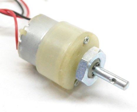
DC motor
L293D
Pin Configuration of L293D
NodeMCU
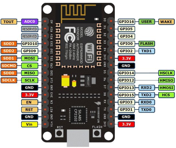
Pin Configuration
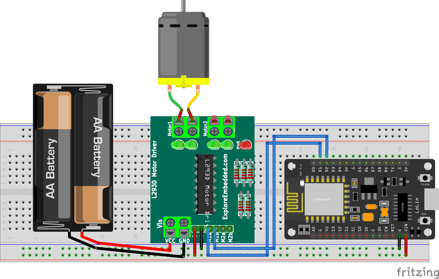
int IN1 = D1;
int IN2 = D2;
void setup() {
  pinMode(IN1,OUTPUT);     // SETS IN1 AS OUTPUT
  pinMode(IN2,OUTPUT);     // SETS IN2 AS OUTPUT
}
void loop() {
  digitalWrite(IN1,HIGH);  // CLOCK-WISE DIRECTION 10 SECONDS
  digitalWrite(IN2,LOW);
  delay(10000);

  digitalWrite(IN1,LOW);  // ANTI-CLOCK-WISE DIRECTION 10 SECONDS
  digitalWrite(IN2,HIGH);
  delay(10000);
}